Python module for MCP23S17 for use with the Raspberry Pi
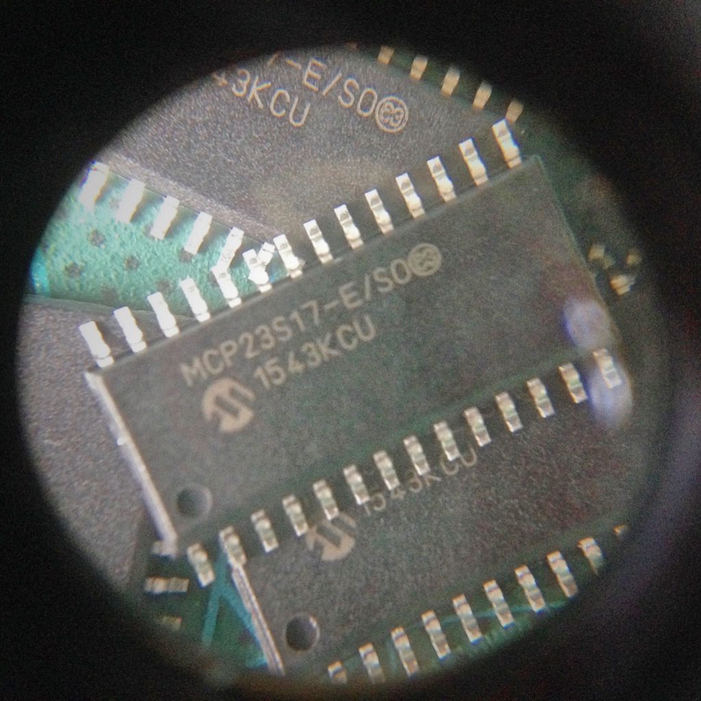
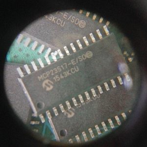 Some time ago I revised the hardware design of the ControlBlock and added test points for all major signals. The overall aim was to build a device for doing final system tests that are done before any single ControlBlock leaves for shipping. These system tests are written in Python. This post is about a Python module for the MCP23S17 to be used on a Raspbbery Pi.
Basically, the tests set various input signal lines to logical high and low values in a specific order and test if certain output signals have the correct level. To do this, another manually tested ControlBlock is used. Since revision 2.X the ControlBlock uses MCP23S17 GPIO expanders to provide 32 input/output lines for arbitrary usage. I did not find any Python abstraction that would allow me to easily access the MCP23S17 from a Raspberry Pi, so I decided to write a Python module myself.
The result is a publicly available Python module, available via PyPI, that you can install with pip.
Installing the Module
If not already done, you need to install PIP via::
[code lang=bash] sudo apt-get install python-dev python-pip[/code]
Then you can install the module from PyPI via
[code lang=bash] pip install RPiMCP23S17[/code]
That’s it!
Interface of the Module
So, how do you use the module. How does its interface look like? Here is a list of the public methods of the module together with brief descriptions:
- Constructor – Initializes an instance given the SPI bus number, the chip-enable (CE) number, and the device ID of the MCP23S17 component.
- open – Opens the configured SPI-bus with hardware-address access and sequential operations mode.
- close – Closes the SPI connection that the MCP23S17 component is using.
- setPullupMode – Enables or disables the pull-up mode for a given input pin.
- setDirection – Sets the direction for a given pin.
- digitalRead – Reads the level of a given pin.
- digitalWrite – Sets the level of a given pin.
- writeGPIO – Sets the 16-bit data port value for all pins.
- readGPIO – Reads the 16-bit data port value of all pins.
You can find a detailed documentation in the Python docstrings of the module.
Exemplary Usage
Here is some demo code that also comes with the module sources. The demo periodically toggles all pins of two MCP23S17 expanders:
[code lang=python] mcp1 = MCP23S17(deviceID=0x00)mcp2 = MCP23S17(deviceID=0x01)
mcp1.open()
mcp2.open()
for x in range(0, 16):
mcp1.setDirection(x, mcp1.DIR_OUTPUT)
mcp2.setDirection(x, mcp1.DIR_OUTPUT)
while (True):
for x in range(0, 16):
mcp1.digitalWrite(x, MCP23S17.LEVEL_HIGH)
mcp2.digitalWrite(x, MCP23S17.LEVEL_HIGH)
time.sleep(1)
for x in range(0, 16):
mcp1.digitalWrite(x, MCP23S17.LEVEL_LOW)
mcp2.digitalWrite(x, MCP23S17.LEVEL_LOW)
time.sleep(1)
[/code]
So, if you are tinkering with MCP23S17 components and Python on a Raspberry Pi, you might find this module to be helpful for you.
You can find the module on PyPi here.
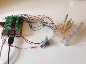
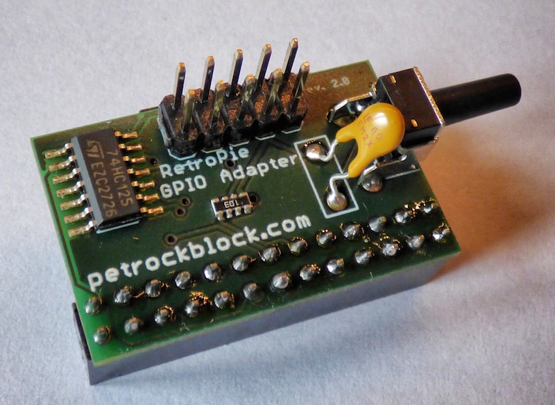
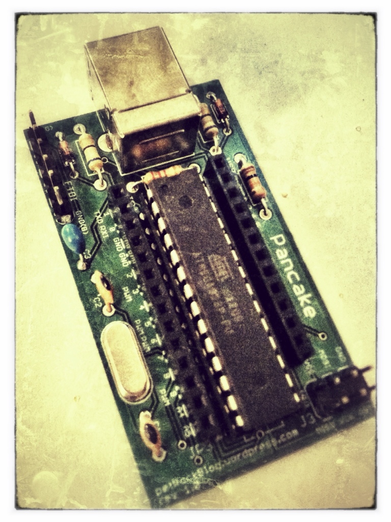
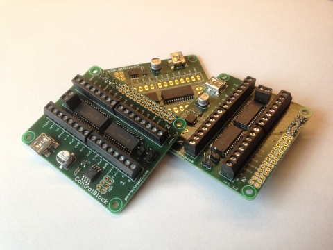
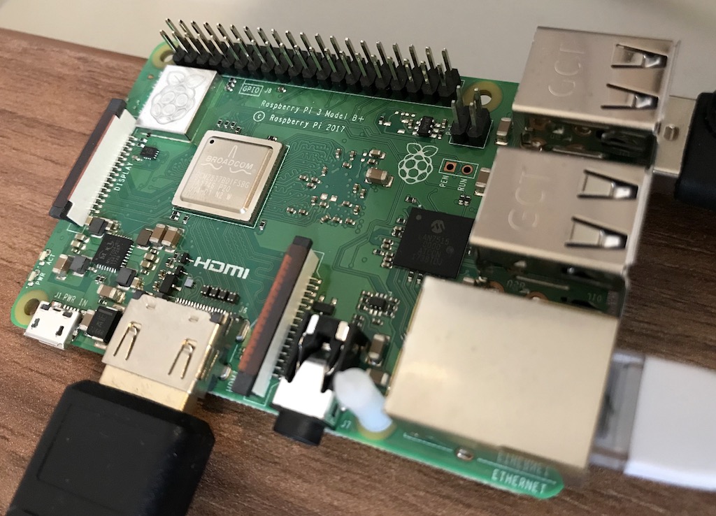
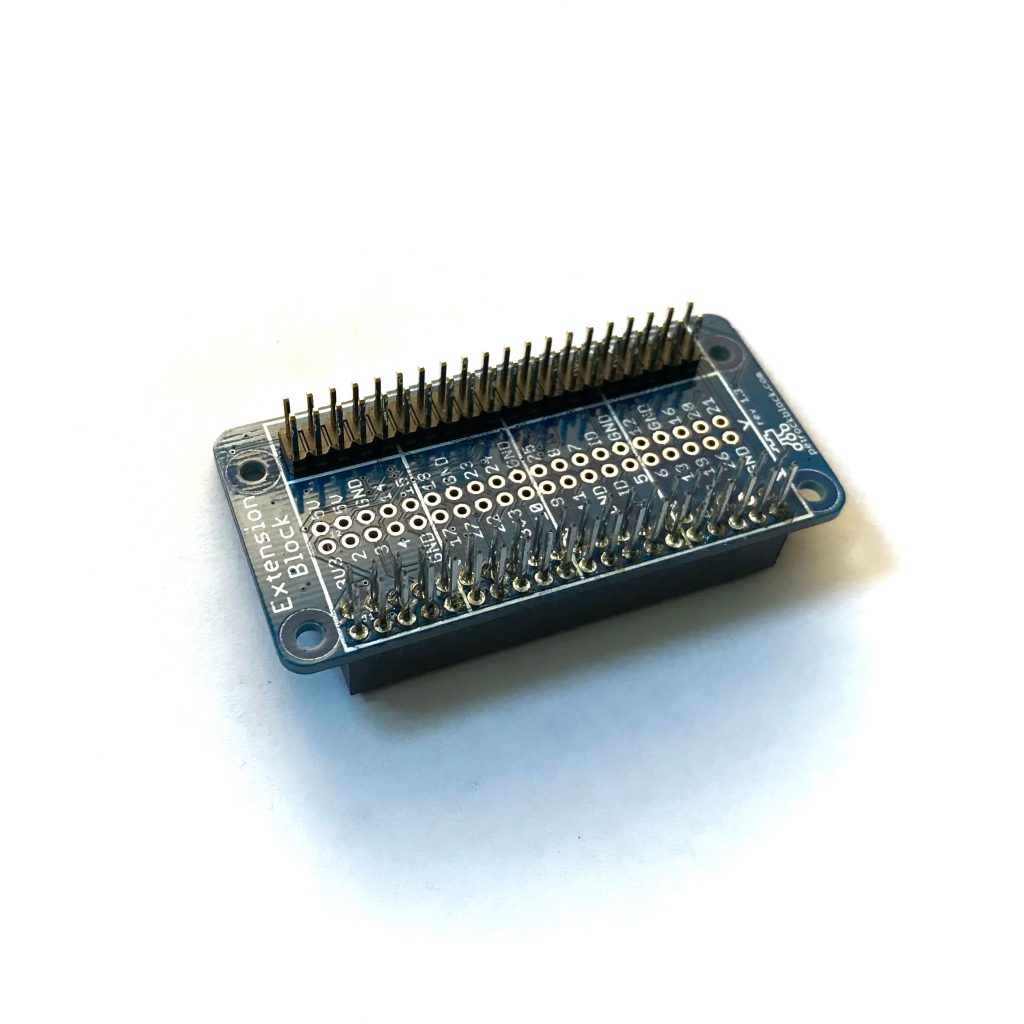
By the way, here is an image of the testing station for the ControlBlocks, which we are using to do the final system tests before shipping:
If no one else is going to thank you, I certainly will. After years of DIY, all of it.. I am trying to make use of the community around the RPi. I was resigned to figure out how to call C code from Python to run a couple MCP23S17s conveniently. Then I happened on to your blog. I am looking at a pridopia board (because I’m trying not to draft one myself) but their test programs bit bang the SPI. I want the same convenient API you do. One thing I will add, and you might consider adding, is a way to set the invert register, probably very similar to the direction code. I designed a board to provide optoisolated 24 V IO for the automation world.
Because the 23S17 inputs have pull ups but no pull downs, I need to invert the inputs so I can use positive logic in and out,
Thanks for the kudos! Good idea with the inverted polarity register. I have added that to the issue list in Github (https://github.com/petrockblog/RPi-MCP23S17/issues/1)